In order to make full use of sub-surface cavities for human activities, an efficiant means of telecommunications back to the surface will be required. With that concept in mind, we have successfully completed the first of a series of tests using the "Node-to-Node Incave Telecommunication System," (NNITS), designed to provide a high-speed networked connection between two computer systems on different ends of a cave.
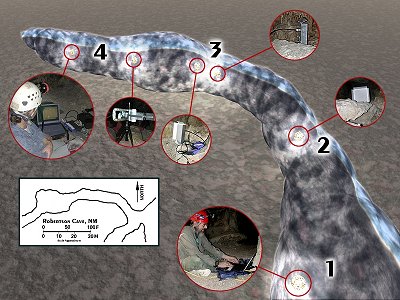
Node-to-Node Incave Telecommunication System Diagram - Click For Detail |
The test equipment consisted of:
- A Toshiba Portege 2000 PC notebook computer running Windows XP operating system near the mouth of the cave, connected via its internal 10/100 BaseT Ethernet adaptor through a 50 foot Ethernet cable to;
- a Linksys 802.11b/g Router/Access Point (model WRT54G) located a bit further into the cave. The router was running in 802.11b (11Mbps) mode connected to an external 16 dB gain Yagi antenna (wireless link segment A) that was pointed further into the cave towards a;
- Repeater station consisting of two Linksys 802.11b wireless bridges, (model WET11) connected to each other with a short Ethernet 10/100 BaseT cable. Each of the 802.11b bridges had a 15.5 dB gain flat panel antenna connected to it, one pointing "in-cave" (wireless link segment A), and one pointing "out-cave" (wireless link segment B). The "in-cave" antenna was pointed towards;
- The network terminus or simulated data collection site. This site consisted of another 16 dB gain Yagi antenna connected to a Linksys 802.11b/g Access Point (model WAP54G), which was in turn connected via a short Ethernet cable to a second laptop, a Sony VAIO, running the Windows 2000 operating system.
For this proof of concept test, the wireless networking equipment was powered by three small uninterruptible power supplies (UPS), each containing a 12 volt, 7 Amp-hour lead acid battery. These UPSs weren't too heavy (about 13 pounds each), and had sufficient capacity to power the 802.11 gear for several hours - much more than we needed to conduct this simple test.
In order to avoid interference, link A used 802.11b channel 6, and link B used the non-overlapping channel 11. At the repeater station, we kept the link A and link B antennas separated by at least 6 feet and pointed in the opposite direction, in order to reduce receiver desensitization, where the receiver on one 802.11 device is made less sensitive by the relatively high power signal from the nearby transmitter on another 802.11 device. This desensitization is a form of interference, and can occur even when the receiver and transmitter are operating on non-interfering channels if the antennas are too close together. Follow the links below for a photo diary of the tests. |
